Analysis of Leakage Causes of 200L Closed Steel Barrel Sealer Shi Zhenzhuang City Barrel Factory Liu Zhenting With the rapid development of China's barrel technology, the quality of 200L closed steel drums has reached the number of manufacturers of the International Maritime Dangerous Regulations Class I packaging standards, and the situation is gratifying. However, due to the widespread use of the triple round crimping process, most manufacturers successfully passed the drop test of 1.8m (the liquid density inside the liquid does not exceed 1.2), while the 250kPa water pressure test results are not satisfactory. Leakage is often generated around the injection hole (see point 3b), and the test results are judged to be inconsistent. The following is a breakdown of the leakage problem of the closure. In the GB325 "Packaging Container Steel Barrel" standard, there are detailed requirements and instructions for the 200L closed steel drum. In GB13251 "Metal Container Steel Bar Closer" standard, except for the thickness of the TG type coil of the sealer, the other requirements are also detailed. However, there are no standard and uniform regulations for the size, structure and key process parameters of the molds used to assemble the top and the coil. Manufacturers with strong technical strength design their own plus more small factories, please ask for the design of external processing. Therefore, there are certain differences in the structure of the molds used in each factory and the selection of key process parameters, and the use effect is also very different. Therefore, whether the mold design is reasonable and whether the worker's operation adjustment is proper is the key to solve the leakage of the sealer, and it is also the focus of our discussion. The following is a brief analysis of the process of creating a leak around the injection hole when performing a 250 kPa water pressure test. During the water pressure test, as the pressure inside the barrel gradually increases, the top plane of the barrel gradually becomes an approximate spherical shape that protrudes outward, as shown in Fig. 1. When the top of the barrel is deformed into a spherical surface, there is no wrinkle at the center of the top of the barrel, and a wavy wrinkle is formed around the top of the barrel, as shown in Fig. 2. The venting holes 1 and the injection holes 2 are just on the pleats. Since the diameter of the vent hole is small, it can barely be in an approximately planar state, and the diameter of the injection hole is large, and the problem is prominent; the thickness of the large coil is about 3 mm, and the mechanical strength is large, and the screwed lid is screwed on the snail. The center of the ring is supported, so the large spiral is basically not deformed. However, the iron around the large spiral of the top of the bucket is involved in deformation and wrinkles. On some of the arc segments, the assembly gap between the two begins to increase, and when it exceeds the elastic range of the inner liner, it begins to leak. Here, by the way, it is important that the test device shown in the GB13251 standard performance test tests the assembly quality of the sealer, and it is also very effective, but because the test simulates the iron sheet area at the top of the barrel is small, and the position of the sealer is According to the center, the iron sheet at the coil does not produce wavy wrinkles, so the test results do not reflect the actual situation when the steel drum is subjected to hydrostatic test. The test equipment that truly simulates the water pressure test of vanadium barrels has yet to be researched and developed by us. Below we analyze the main causes of leaks in the closure. First, the mold design is not reasonable 1. A cross-sectional view of a properly assembled closure is shown in Figure 3. Saw the assembled closure to observe its profile. If there is a gap at point a in Figure 3, the height of the punched flange at the top of the bucket is not enough. The main structure of the composite mold for punching and drawing is shown in Fig. 4. The main factor affecting the height of the flange is the size of the punch punch diameter in Figure 4. The diameter of the punching hole is selected to be large, and the height of the flanging is not enough; the diameter of the punching hole is selected to be small, and the height of the flanging is extremely high, which is easy to crack (increasing the R angle of the flanged punch properly can also effectively reduce cracking). I carried out the experimental conclusion by theoretical calculation and using the barrel plates of different materials. The diameter of the punch of the injection hole is φ50±2mm. The diameter of the venting punch punch is φ19±1 mm. Each manufacturer should reduce the tolerance according to the model of the closure used and the actual condition of the barrel steel. Taking the injection hole as an example, if the TG type spiral barrel plate is used, the 08 steel cold-rolled plate is used, and a φ48+0.5 mm punching punch can be selected. If a TM type coil is used, the barrel plate uses a hot-rolled oil drum plate, and the punching punch can be set to φ62-0.5 mm. 2. In Fig. 3, the thickness of the liner before compression is 2.7-3 mm, and when the thickness after compression is greater than 1.5 mm, the performance of leakage prevention is greatly reduced, indicating that the value of the eight-degree drawing depth h in Fig. 4 is too large. When using the TM type coil, the h value should be 4.5+0.1mm, and the h value should be 4.2+O.1mm when using the TG type coil. 3. When the R angle at d in Fig. 3 is too large, the drawing is smooth. Since most of the collar is filled with the R arc angle space, the impermeability is reduced. Therefore, in the case where the drawing does not crack, the R drawing angle here should be minimized, and R = R1 - 1.5 mm can be taken. 4. After the coil is assembled, the lower plane of the coil is lower than the lower plane of the top of the bucket, not "inner flat" but "inner". If the depth of the eight-part drawing is correct, the main reason for the 'inner-out type' is that the design of the press-fit assembly is unreasonable or the pressure is not sufficient. The main structure of the mold used in this process is shown in Figure 5. The working profile is pressure. The circle first compacts the top of the bucket, the liner ring and the spiral ring and presses the enjoyment of the collar to about 1.5mm with sufficient pressure. At this time, the spiral flange hooks the bucket. In a word, the mold It must be compacted first, then the edge is hooked tightly. If the mold structure is too simple, there is no function of pressing first, or the strength of compaction is not enough, it is difficult to ensure the quality of assembly. Second, the mold wear is seriously not replaced in time In Fig. 3, the gap at point C is that the inner hole of the drawing die is seriously worn, and the diameter thereof becomes larger. The d point liner runs into the R arc, which is the drawing of the drawing die R. The drawing angle is severe, and the R is changed. Caused by big. If the mold with severe wear is not replaced in time, it is difficult to ensure the quality of the assembly, and it is impossible to pass the 250kpa water pressure test. Third, improper adjustment of equipment operation Mainly the stroke adjustment of the press. The locking device of the device is not reliable and the adjusted stroke has changed. This should strengthen the self-test of the process. In general, the total height after assembly (h in Figure 3) is: As long as the operator self-checks these dimensions at any time, the assembly quality can be guaranteed. Finally, the selection of the closure is explained: 1. Is it better to use the ordinary threaded TM type closure for the barrel, or is it better to use the tube threaded TG type closure? Generally speaking, the TG-type sealing device has a wide side (the large spiral is 87.8mm wide), but the material is slightly thinner (δ=2.65mm), and the thread is an inch pipe thread multi-TM type closeder. Narrow (large spirals are squared at 75mm wide), but the material is thicker (δ=3) and the threads are metric threads. I think that these two types of closures can meet the requirements of the International Maritime Dangerous Regulations package. Conversely, the examples of users of these two closures that did not pass the water pressure test also existed. The key is the assembly quality of the closure and the design quality of the mold and the quality of the operator. If your product is mainly for domestic sales, it is recommended to use the common thread TNJ type for domestic exchange. If your product is mainly for export, especially for export to Europe and America, it is recommended to use the British pipe thread TG type because the inch tube Threaded barrels are used more abroad. 2. Some manufacturers are insured for safety, and the screw ring press assembly is also applied to the seal liner in addition to the set liner. I don't think there is a need, one will increase the production cost and the other will have a bad effect. Because the volume of the glue occupies valuable space during the press-fit assembly. Due to the limited solid content of the glue, the volume of the glue shrinks to form a new void after drying, which causes it to leak during the hydraulic test and is self-defeating. Makeup Egg,Spongebob Egg,Makeup Egg Sponge,Sponge Egg DONGGUAN YACAI COSMETICS CO.,LTD. , https://www.yacaicosmetic.com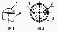

Analysis of Leakage Causes of 200L Closed Steel Barrel Sealer
Next Article
Pay attention to the social makeup point minefield
Prev Article
Home enters the "micro-profit era" 2011 home trends